Compact Circuit Breakers – Understanding the Tripping Characteristics
Low-voltage circuit breakers are used to protect low-voltage installations, cable lines, and connected equipment against overloads and short circuits. On the market, we encounter two different types of compact circuit breakers: those with thermo-magnetic (electromechanical) trip units and those with electronic trip units.
Thermo-magnetic compact circuit breakers operate based on a bimetal element and an electromagnetic trip mechanism. In the case of an overload current, due to the physical properties of the bimetal, it gradually bends until the circuit breaker trips. In the event of a short circuit, a strong magnetic force is generated, which activates the electromagnetic trip mechanism.
Overload and Short Circuit
Below, the difference between an overload and a short circuit is explained using a simple example.
An overload of a conductor or cable is a condition in which the electric current flowing through it exceeds the permissible current of that cable. Based on the expected load of each circuit, the designer selects the appropriate cable cross-section, and accordingly, a suitable circuit breaker is chosen (the selection of the rated current setting in amperes is crucial).
If the current exceeds the permissible current of the cable, the circuit breaker must disconnect the circuit.
For example: the circuit breaker is set to 63 A, and the selected cable is NYY 4 × 25 mm². At a certain moment, a current of 100 A flows, which is too high for the selected cable. This can reduce the lifespan of the insulation, and in unfavorable cases, an overloaded cable may even cause a fire.
In the case of a short circuit, either between all three phases (three-pole short circuit) or between the phase and neutral conductor (single-pole short circuit), due to very low impedance, a short-circuit current of several thousand amperes flows. In such a case, the circuit breaker trips instantaneously (within a few milliseconds).
Basic Settings of LV Circuit Breakers
Electromechanical trip units are still commonly used in circuit breakers with lower rated currents (up to 250 A) due to their lower cost. The main disadvantage of these trip units is their limited adjustment range, which means that the breaker must be carefully selected according to the characteristics of the protected device.
The adjustment range of the overload trip (Ir) is typically (0.63 to 1) × In (rated current).
The adjustment range of the short-circuit trip (Ii) is usually (6 to 10) × In (Figure 3).
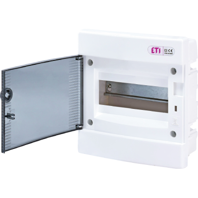
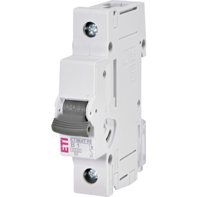
There are also smaller and more affordable circuit breakers without adjustable short-circuit protection, where this function is factory preset (see Figure 4).
The adjustment range of electronic trip units is much wider:
Overload trip (Ir): typically (0.4 to 1) × In
Short-circuit trip (Ii): typically (2 to 12) × In
On the I–t characteristic curve shown in Figure 2, the overload range (63–100 A) and the short-circuit range (6–10 × In) of the tripping characteristic are shown.
Figure 3 shows the settings using the ETI Curve software.
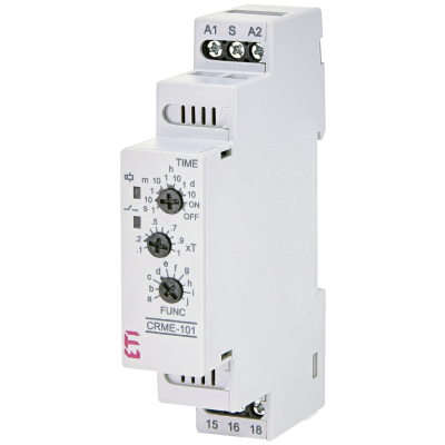
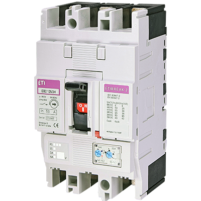
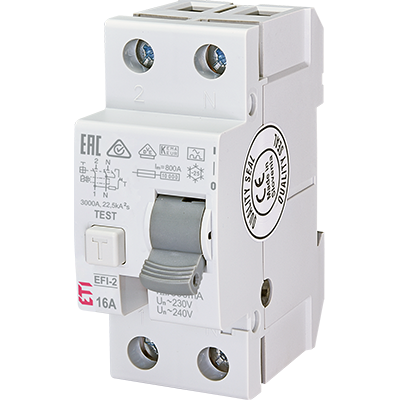
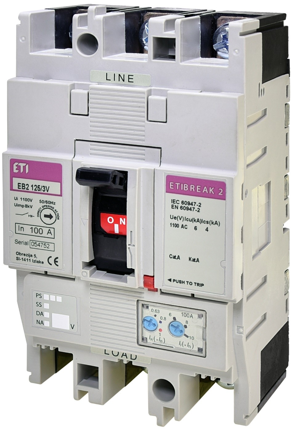
If we observe Figure 1 (our circuit breaker) and Figure 2, the characteristic values for the basic settings of the circuit breaker are as follows:
In – rated current of the circuit breaker (in our case 100 A)
Ir – overload trip, adjustable from (0.6 to 1) × In (in our case 63 A to 100 A)
Ii – short-circuit trip, adjustable from (6 to 10) × In (in our case 600 A to 1000 A)
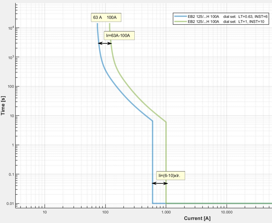
Standardized I–t tripping characteristic of an LV circuit breaker (In = 100 A)
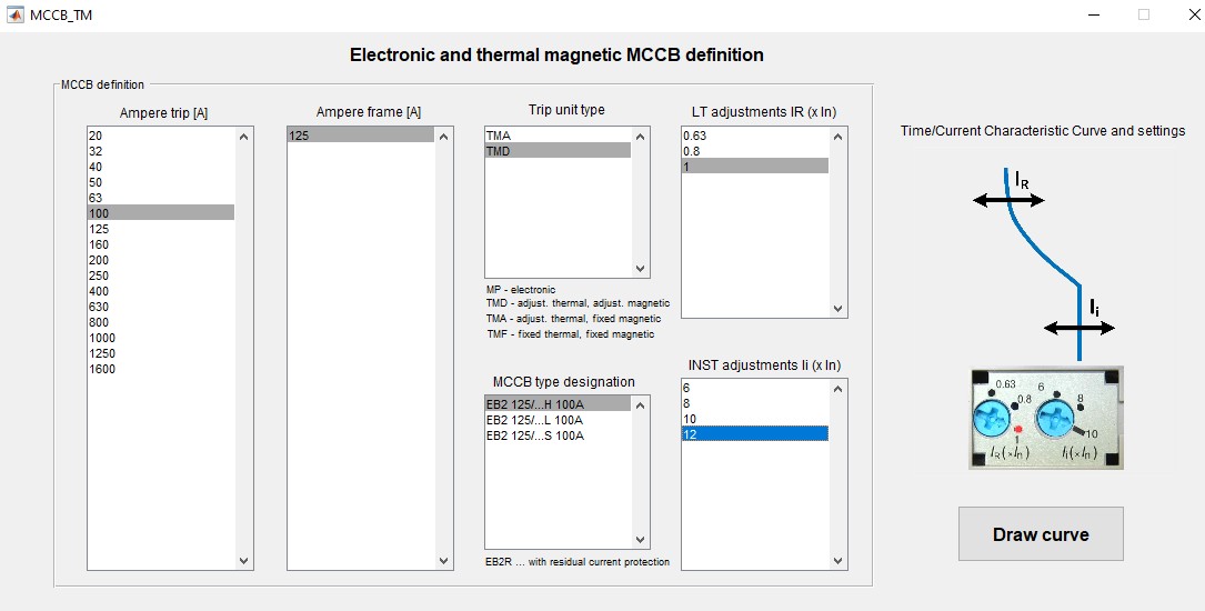
Example of LV circuit breaker settings
Next image shows an example of a circuit breaker without adjustable short-circuit protection (Ii), as it is factory preset.
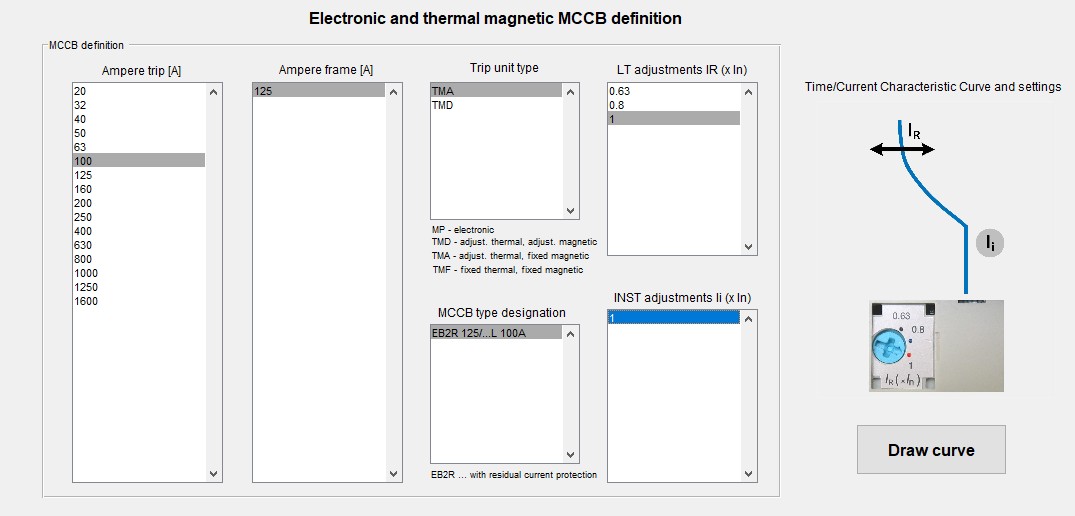
Example of LV circuit breaker with factory-set short-circuit protection
Tripping Time in Overload Conditions
A common question is: At what time does the bimetallic trip operate in the case of an overload?
If we assume that the overload trip is set to 63 A, and an overload current of 100 A flows through it, the tripping time is approximately 350 seconds.
In the case of a short circuit, the tripping would be instantaneous, approximately 10 ms, as shown in picture below.
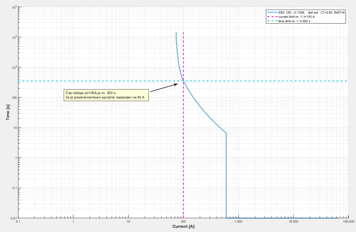
Diagram showing the dependence of tripping time on overload current
Can the Setting Be Increased to 100 A?
The question often arises whether the current setting can be increased to 100 A.
The answer is no.
If the designer has specified a load current of 63 A or less, both the setting of the circuit breaker and the cable cross-section were selected accordingly. Any change to the current setting must be approved by the designer, who must verify the suitability of the protection by recalculating the appropriate relationship between the breaker setting and the cable cross-section.
Advanced Settings of LV Circuit Breakers
In practice, more demanding protection challenges arise, such as:
Heavy motor starting,
Selectivity problems,
Cable protection under special conditions.
In such cases, we use LV circuit breakers that, in addition to basic settings, offer additional adjustable protection functions, allowing us to solve issues such as selectivity.
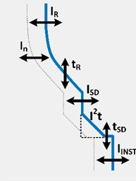
Image shows a typical I–t characteristic curve that includes both basic and advanced settings. These advanced protection concepts will be explained in one of the next articles.